
Understanding URDF: Building the Blueprint of Your Robot

Introduction
You want to start building a robot, or maybe you already have one. Either way, there’s one thing you’ll need to describe your robot to the digital world: a Unified Robot Description Format (URDF). Whether you're planning to simulate your robot in Gazebo, visualize it in RViz, or define its structure for control and navigation, the URDF is where it all begins.
Think of URDF as the blueprint of your robot. Just like architects use plans to design buildings, roboticists use URDF to describe every part of a robot, its body, joints, and how everything is connected. In this blog, I’ll walk you through the essentials of URDF, show how it fits into robotics projects, its syntax and even guide you through building your first robot description in a follow up blog.
Importance of URDF
URDF is not optional in most ROS-based robotics systems it's essential. Here's why:
1. Defines Robot Structure
It tells ROS what your robot looks like, how its parts move, and how they relate to each other.
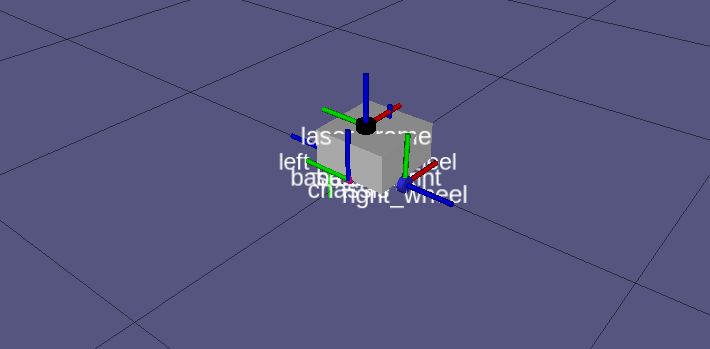
2. Builds the TF Tree
URDF enables generation of the TF (Transform) tree — the coordinate frames of your robot that allow movement tracking and localization.
3. Enables Simulation
Tools like Gazebo and Ignition use URDF (or SDF) to simulate robot physics, sensors, and control.
4. Aids in Visualization & Debugging
You can visualize the URDF in RViz, view the transform hierarchy with urdf_to_graphviz, and debug frame issues easily.
5. Powers ROS Integration
URDF is the starting point for integrating with navigation, control, SLAM, motion planning, and more.
URDF Basics
URDF is an XML-based format used in ROS (Robot Operating System) to describe the physical structure of a robot, its parts, how they’re connected, how they move, and how they look. In simple terms, URDF is like a blueprint for your robot, but instead of being on paper, it’s written in code that ROS and simulation tools can understand.
Key Elements of a URDF
<robot>: The root element of the URDF file
<link>: Represents a rigid part of the robot
<joint>: Describes the connection between two links
<visual>: Specifies what the robot part looks like
<collision>: Defines the shape used for detecting interactions
<inertial>: Includes mass and moment of inertia for simulation
Below is a simple example:
<robot name="my_robot">

  <!--- BASE LINK -->
    <link name="base_link">

    </link>

  <!--  CHASSIS LINK -->
   <joint name="chassis_joint" type="fixed">   <!--Connects two links-->
        <parent link="base_link" />
        <child link="chassis" />
        <origin xyz="-0.1 0 0" />
    </joint>

 <link name="chassis">

    <!-- Visual: Appearance in RViz -->
    <visual>
      <geometry>
        <box size="0.4 0.4 0.1"/> <!-- Width x Depth x Height in meters -->
      </geometry>
      <material name="gray">
        <color rgba="0.5 0.5 0.5 1.0"/> <!-- Gray color with full opacity -->
      </material>
    </visual>

    <!-- Collision: Shape used in simulation for collision detection -->
    <collision>
      <geometry>
        <box size="0.4 0.4 0.1"/>
      </geometry>
    </collision>

    <!-- Inertial: Physical properties used in physics simulation -->
    <inertial>
      <mass value="2.0"/>
      <origin xyz="0 0 0" rpy="0 0 0"/>
      <inertia ixx="0.01" ixy="0" ixz="0" iyy="0.01" iyz="0" izz="0.01"/>
    </inertial>

  </link>

  <!-- Joint: Right Wheel -->
  <joint name="right_wheel_joint" type="continous">
    <parent link="base"/>
    <child link="right_wheel_link"/>
    <origin xyz="0 -0.2 -0.05" rpy="0 0 0"/>
    <axis xyz="0 1 0"/>
  </joint>

  <!-- Right Wheel Link -->
  <link name="right_wheel_link">
    <!--link description-->
  </link>

</robot>
We will breakdown the above urdf code into parts explaining what each part entails.
Anatomy of a URDF
It consists of:
1. The Root Element <robot>
Every URDF file starts with a <robot> tag and ends with a </robot>. It wraps everything that defines your robot.
<robot name="my_robot">
  ...
</robot>
2. A Physical Component <link>
A link is any rigid part of the robot, that is, a base, a wheel, a sensor mount, an arm segment, etc. It represents a single, unmoving body in the robot’s structure.
<link name="base_link">
  ...
</link>
3. The Connections Between Links <joint>
A joint connects two links and defines how one moves relative to the other.
<joint name="right_wheel_joint" type="continous">
  <parent link="base_link"/>
  <child link="right_wheel"/>
  ...
</joint>
Common joint types include:
fixed– No movement (e.g. attaching a sensor)revolute– Rotating like a wheel or elbowcontinuous– 360° rotation (no limits)prismatic– Sliding like a drawer
Every robot with multiple links must connect them with joints to form a kinematic chain, which is the mechanical structure that connects parts of a robot in a way that allows them to move relative to one another.
4. What You See in RViz <visual>
This section describes the 3D appearance of the link, the shape, size, and color that gets rendered in visualization tools like RViz. It is nested inside a <link> .
<visual>
  <geometry>
    <box size="0.4 0.4 0.1"/>
  </geometry>
  <material name="gray">
    <color rgba="0.5 0.5 0.5 1.0"/>
  </material>
</visual><geometry>: Specifies the shape. Here, a box 40cm wide and deep, and 10cm high.<material>: Assigns a visual color (gray, with full opacity).
5.What the Robot Bumps Into <collision>
This defines the shape used by simulators like Gazebo to calculate collisions with objects. It keeps simulation fast and realistic.
<collision>
  <geometry>
    <box size="0.4 0.4 0.1"/>
  </geometry>
</collision>
Why it matters: Without this, your robot will pass through walls and objects in simulation or not interact with anything physically.
6. How the Robot Behaves Physically <inertial>
This section defines mass, center of gravity, and inertia — all essential for realistic physics simulation. Basic description is as follows:
<inertial>
  <mass value="2.0"/>
  <origin xyz="0 0 0" rpy="0 0 0"/>
  <inertia ixx="0.01" ixy="0" ixz="0" iyy="0.01" iyz="0" izz="0.01"/>
</inertial>mass: Gives the weight of the link in kilograms.origin: States the position of the inertial frame relative to the link's frame.inertia: Gives a mathematical description of how the object resists rotation. One can use online tools to calculate this.
If you skip this section, Gazebo may issue warnings or simulate unrealistic movements (like your robot flying away or collapsing).
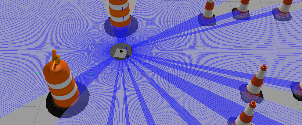
Attached below is a video showing the simulation of my URDF in Rviz and Gazebo:
Common URDF Pitfalls and Troubleshooting Tips
1. Forgetting Inertial Properties
Problem: Gazebo shows erratic behavior, or throws errors like:
Warning: Link 'base_link' has no inertial tag.Fix: Always include the
<inertial>block for each link when simulating in Gazebo. Even approximate values are better than nothing.
2. Incorrect Joint Parent/Child Order
Problem: TF tree doesn’t build correctly or robot moves unexpectedly.
Fix: Remember:
parentis the fixed link.childis the moving link.
Tip: Think of the joint as saying, "This child moves with respect to this parent."
3. Missing or Duplicate TF Frames
Problem: RViz errors like:
No transform from [wheel_link] to [base_link]Fix:
Make sure your TF tree is complete and acyclic.
Use
ros2 run tf2_tools view_framesto visualize your TF tree and find missing or circular transforms.
4. Links Not Connected by Joints
Problem: Some parts of the robot don’t appear in RViz or aren’t simulated.
Fix: Every link (except the root/base) must be connected via a joint to form a complete tree.
5. Joint Limits Misconfigured
Problem: Joints don’t move, or simulation crashes.
Fix:
Make sure
revoluteorprismaticjoints have valid<limit>tag:
<limit effort="10" velocity="1.0" lower="-1.57" upper="1.57"/>Use
continuousif you want unlimited rotation (e.g. wheels).
Conclusion
Now that you understand what a URDF is and how it works, you're ready to start building your own robot model. In the next part of this series, we’ll walk through creating a complete URDF robot step by step.
Stay tuned, your robot-building journey is just beginning!