
INTRODUCTION TO SIMULTANEOUS LOCALIZATION AND MAPPING

Introduction
SLAM (simultaneous localization and mapping) is a technique for creating a map of environment and determining robot position at the same time. It is widely used in robotics. While moving, current measurements and localization are changing, in order to create map it is necessary to merge measurements from previous positions. To perform an accurate and precise SLAM, one of the simplest solutions is to use a laser scanner and an odometry system (speed measurement system based on encoder data). However, due to the imperfections of the sensors, the map creation process is much more difficult. Why? Because various imperfections, e.g. caused by wheel slippage, can cause the same wall to be classified as two objects. To counteract unwanted changes, these algorithms use various tricks, such as the Monte Carlo method.
Install Nav2 and slam_toolbox
First, let’s install the Navigation 2 packages.
sudo apt install ros-humble-navigation2 ros-humble-nav2-bringupWe will also install the Turtlebot3 packages as we’ll use this robot as an example.
sudo apt install ros-humble-turtlebot3*Once you have this, let’s install the ROS2 slam_toolbox package.
sudo apt install ros-humble-slam-toolboxEverything is now correctly installed and setup.
Start the ROS2 stack for your robot
Now you can start your robot. In this tutorial I will use Turtlebot3. You can follow along with this example, and then you’ll have to use your own robot stack here. Note that adapting a robot to the Navigation 2 stack is not something trivial, and I’m not going to talk about this here, as it could fit an entire course.
So, when you want to use your own robot, make sure that you can start the robot, control it (with keyboard, joystick, …), and have a LaserScan message published on a /scan topic. Those are the main requirements for slam_toolbox to work.
Now, back to the Turtlebot3.
Start the robot
To start the Turtlebot3 stack, we first need to export an environment variable to specify which version we want to launch (burger, waffle, waffle pi). We’ll use the waffle version.
Run this command, or simply add it somewhere at the end of your .bashrc:
export TURTLEBOT3_MODEL=waffle. Now, if you’ve just added the environment variable, make sure to either source the .bashrc or open a new terminal.
As I will do this tutorial without a real robot, I will use a Gazebo simulation of the robot. Let’s start this simulation.
ros2 launch turtlebot3_gazebo turtlebot3_world.launch.pyMaking sure there is a /scan topic
If we list the topics:
ros2 topic list

/camera/camera_info
/camera/image_raw
/clock
/cmd_vel
/imu
/joint_states
/odom
/parameter_events
/performance_metrics
/robot_description
/rosout
/scan
/tf
/tf_static
As you can see, we have a /scan topic. And if we check the type:
ros2 topic info /scan

Type: sensor_msgs/msg/LaserScan
Publisher count: 1
Subscription count: 0
Great, we found the LaserScan message type from the sensor_msgs packages.
With this, we know that our robot is correctly configured for slam_toolbox.
Start Nav2 and ROS2 slam_toolbox
For this we will need 4 terminals.
In the first terminal you have already started the ROS2 stack for your robot. Using the Turtlebot3 example:
ros2 launch turtlebot3_gazebo turtlebot3_world.launch.pyIn a 2nd terminal, start the Navigation 2 stack. Note: if you are using Gazebo, add “use_sim_time:=True” to use the Gazebo time. If using the real robot, skip this argument.
ros2 launch nav2_bringup navigation_launch.py use_sim_time:=TrueIn the 3rd terminal, start the slam_toolbox. Note: same as previously, if using Gazebo, add the argument to use the simulation time.
ros2 launch slam_toolbox online_async_launch.py use_sim_time:=TrueEverything is launched correctly. Now, all you see is a bunch of logs in different terminals. In the 4th terminal we will start RViz, so that you can visualize what’s going on.
To make it easier, we can start with an already existing RViz configuration for Nav2. Otherwise you’d start with nothing and you’d have to configure everything by yourself.
ros2 run rviz2 rviz2 -d /opt/ros/humble/share/nav2_bringup/rviz/nav2_default_view.rvizWith this, you should see a window like that.
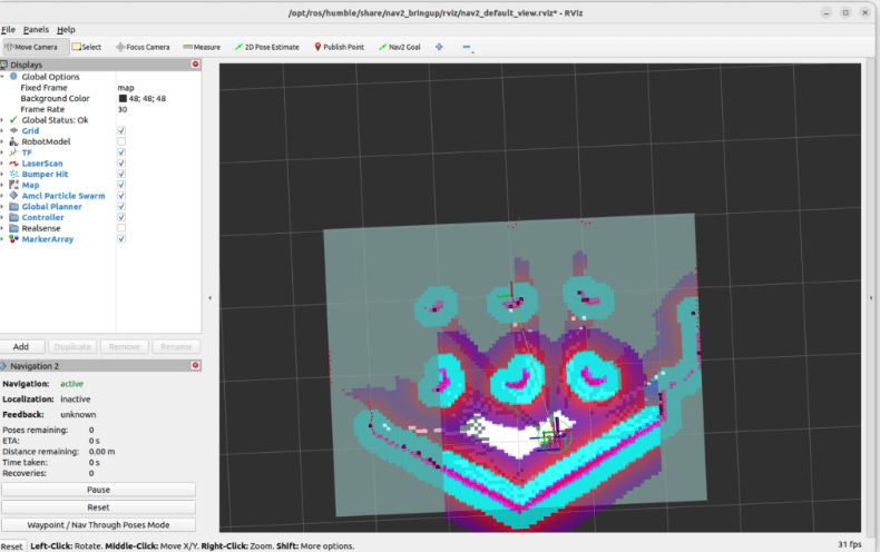
As you can see on the left menu, a lot of stuff is already configured: TF, LaserScan, AMCL, global and local planner, etc. To get a better view for SLAM, I’ll uncheck the “Global Planner” and the “Controller” (local planner).
Generate a map with slam_toolbox
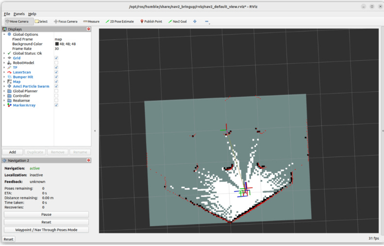
As you can see on the previous screenshot, we have 3 possible colors for any pixel in the map:
white: free space.
black: obstacle.
grey: unknown.
Now all we need to do is to make the robot move in the map, so that the grey (unknown) pixels will turn white or black. When we have a result that satisfies us, we can save the map.
Make the robot move around
So, you need to start the node to move your robot, either with a keyboard, joystick, etc. This can also be a node to make the robot explore on its own. Basically, anything that will make the robot move around.
I will open another terminal (5th one). To make the Turtlebot3 move using the keyboard:
ros2 run turtlebot3_teleop teleop_keyboardNow make the robot move around.
Here’s the map that I got after 20-30 seconds:
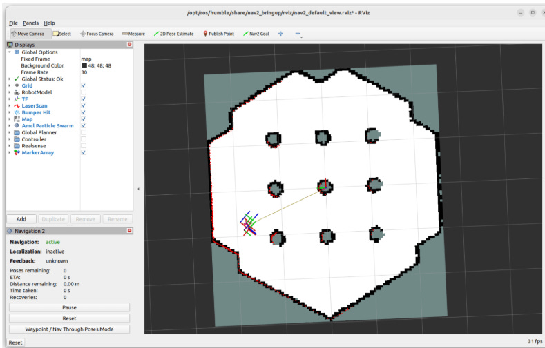
As you can see, all the free space is in white. For some of the obstacles in the middle/right, however, the shape of the circles is not complete – some black pixels are missing.
I could make the robot move everywhere to be sure all pixels are covered, but a result like this should not be a problem when using this map for Navigation. You don’t necessarily need to clear 100% of the pixels to get a good result.
Save the map
Once you get a good enough looking map, you can save it.
And before you save the map, make sure you don’t stop any of the first 4 terminals, otherwise you’d have to start everything again! (however you can stop the 5th terminal, in which you made the robot move.)
To save the map:
ros2 run nav2_map_server map_saver_cli -f my_mapYou can provide an optional “-f” option to specify the path/name of the map. Make sure you don’t put any extension here, this will be done automatically.
When you run the command, you’ll see some logs in white and yellow.
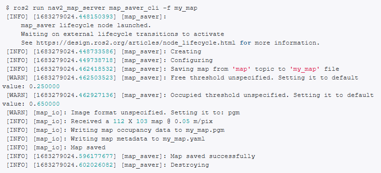
If you have something that looks like that, all good! If you have some error logs in red however, I suggest you try to run the command a few more times.
Now, you should have 2 new files:
my_map.yaml: this file contains the metadata for the map, as well as the path to the image file.
my_map.pgm: this is the image file with white, black and grey pixels, representing the free, occupied, and unknown space.
Next steps with the generated map
Great, you have now successfully generated a map with the ROS2 slam_toolbox package. This package is usually working quite well and is quite fast to generate the map (compared to other packages such as cartographer).
The next steps for you are:
Use the generated map with Navigation 2, to give navigation goals and make the robot move autonomously while avoiding obstacles.
If you have a custom robot, adapt the robot for Nav2, so that you can use it with slam_toolbox.
SLAM configuration
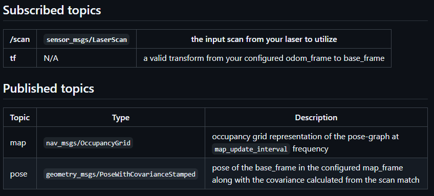
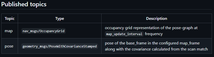
There are many parameters provided by async_slam_toolbox_node node. All the parameters are in the slam_toolbox github repository, and the most important ones are described below.
base_frame- name of frame related with robot, in our case it will bebase_link,odom_frame- name of frame related with starting point, in our case it will beodom,scan_topic- name of topic with sensor data, in our case it will be/scan_filtered,resolution- resolution of the map in meters, in our case it will be set to0.04,max_laser_range- the maximum usable range of the laser, in our case it will be12.0metersmode- mapping or localization mode for performance optimizations in the Ceres problem creation
All above parameters we set in dedicated yaml file in new config folder for example:
slam:
  ros__parameters:

    # Plugin params
    solver_plugin: solver_plugins::CeresSolver
    ceres_linear_solver: SPARSE_NORMAL_CHOLESKY
    ceres_preconditioner: SCHUR_JACOBI
    ceres_trust_strategy: LEVENBERG_MARQUARDT
    ceres_dogleg_type: TRADITIONAL_DOGLEG
    ceres_loss_function: None

    # ROS Parameters
    odom_frame: odom
    map_frame: map
    base_frame: base_link
    scan_topic: /scan_filtered
    # mode: mapping # It will be set in launch file
    debug_logging: false
    throttle_scans: 1
    transform_publish_period: 0.02 # If 0 never publishes odometry
    map_update_interval: 2.0
    resolution: 0.04
    max_laser_range: 12.0
    minimum_time_interval: 0.1
    transform_timeout: 0.2
    tf_buffer_duration: 20.0
    stack_size_to_use: 40000000
    enable_interactive_mode: false

    # General Parameters
    use_scan_matching: true
    use_scan_barycenter: true
    minimum_travel_distance: 0.3
    minimum_travel_heading: 0.5
    scan_buffer_size: 10
    scan_buffer_maximum_scan_distance: 7.0
    link_match_minimum_response_fine: 0.1
    link_scan_maximum_distance: 1.0
    loop_search_maximum_distance: 3.0
    do_loop_closing: true
    loop_match_minimum_chain_size: 10
    loop_match_maximum_variance_coarse: 3.0
    loop_match_minimum_response_coarse: 0.35
    loop_match_minimum_response_fine: 0.45

    # Correlation Parameters - Correlation Parameters
    correlation_search_space_dimension: 0.5
    correlation_search_space_resolution: 0.01
    correlation_search_space_smear_deviation: 0.1

    # Correlation Parameters - Loop Closure Parameters
    loop_search_space_dimension: 8.0
    loop_search_space_resolution: 0.05
    loop_search_space_smear_deviation: 0.03

    # Scan Matcher Parameters
    distance_variance_penalty: 0.5
    angle_variance_penalty: 1.0
    fine_search_angle_offset: 0.00349
    coarse_search_angle_offset: 0.349
    coarse_angle_resolution: 0.0349
    minimum_angle_penalty: 0.9
    minimum_distance_penalty: 0.5
    use_response_expansion: true
The structure of config file
The configuration file should start with the node name. Note: If the name is not exactly the same as the node name, the parameters will not be loaded. After the node name, enter ros__parameters (there are two _ characters in the name). From the next line, enter the names and values of the parameters.
*If you are using namespace you should add name of namespace in the first line. Example:
namespace_name:
  node_name:
    ros__parameters:
      param1: value1
      param2: value2
      ...